GE TRAM-RAC 4A
Note: This connection collects analog signals from the 15-pin ANALOG OUT connector on the rear of the TRAM-RAC 4A. An analog-to-digital converter (ADC) is required to record these signals on a PC. The TRAM-RAC 2 does not provide this analog output.
| Cable | Adapter | Port | VR Device Name |
|---|---|---|---|
| Custom 15-pin D-sub male cable and ADC | — | 15-pin ANALOG OUT | Select the device type for your ADC |
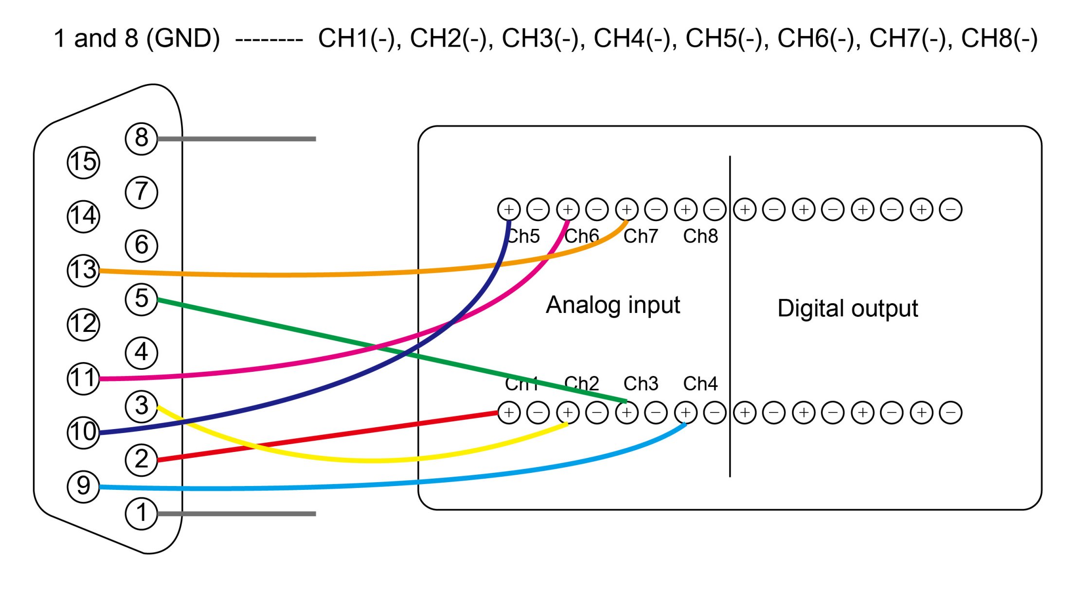
Cable Pinout
Connection Requirements
- An ADC supported by Vital Recorder, connected to the PC via USB.
- A custom cable connecting the required ANALOG OUT pins to the ADC's analog inputs.
- The TRAM module in the top slot for the TRAM outputs listed below.
DATAQ DI-149 and DI-155 have been used with this setup. SNUADC is an alternative with eight analog input channels and support for wired or wireless event-marker buttons.
Connection Steps
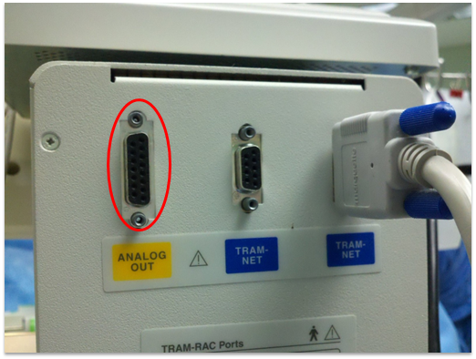
- Locate the ANALOG OUT connector on the rear of the TRAM-RAC 4A housing. It is a 15-pin D-type connector (yellow label), next to the two DB-9 TRAM-NET ports.
- Build or order a cable that routes the ANALOG OUT pins to the ADC's analog inputs as shown in Cable Pinout. Only the pins you actually need have to be wired.
- Connect the finished cable to the ADC's analog input terminals, then connect the ADC to the PC over USB.
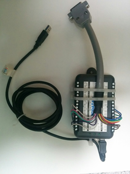
- SNU-ADC is an in-house 8-channel ADC built to avoid that cost. Besides the 8 analog channels it accepts a wired or wireless push button for event markers.
<img src="../hardware_images/ge_tram_rac_4.png" width="450" alt="SNU-ADC board — USB-B connector on one bracket and the D-type analog input connector on the other">Device Configuration
No configuration is required on the TRAM-RAC — the analog outputs are always live. All setup happens on the ADC side in Vital Recorder: channel mapping, gain and unit (see Notes for the scaling values).
Connection Setup for PLETH and CVP
- Confirm that each channel in Vital Recorder contains the expected waveform. In the example below, CVP is recorded on the channel labeled PLETH, while the CVP channel does not show the expected signal.
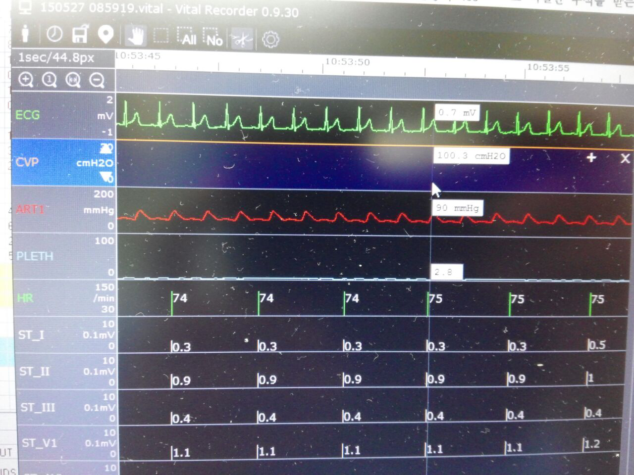
- BP2 connected: the CVP transducer cable is connected to BP2, so pin 13 outputs CVP instead of PLETH.
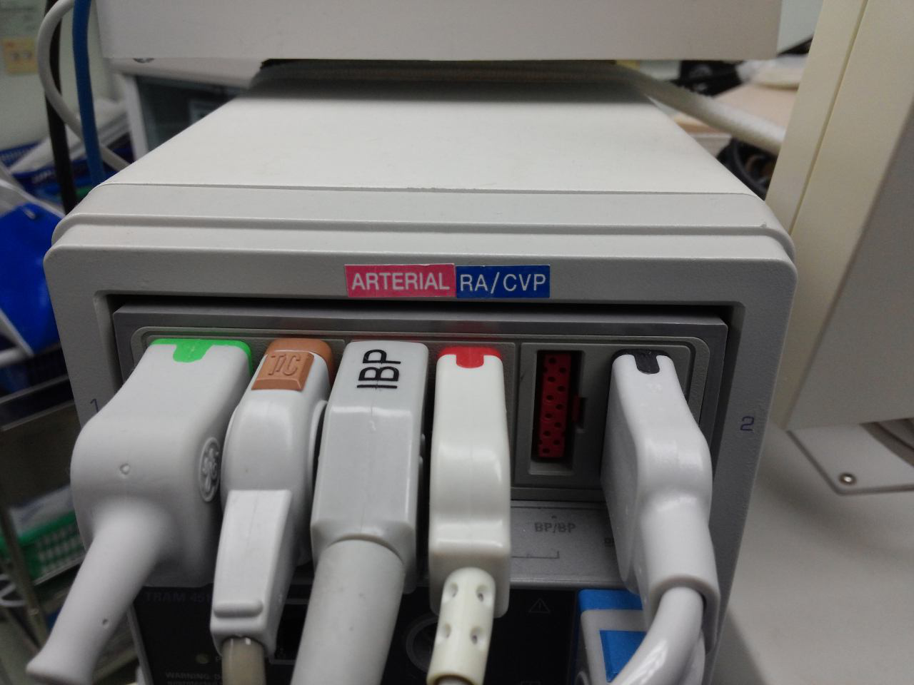
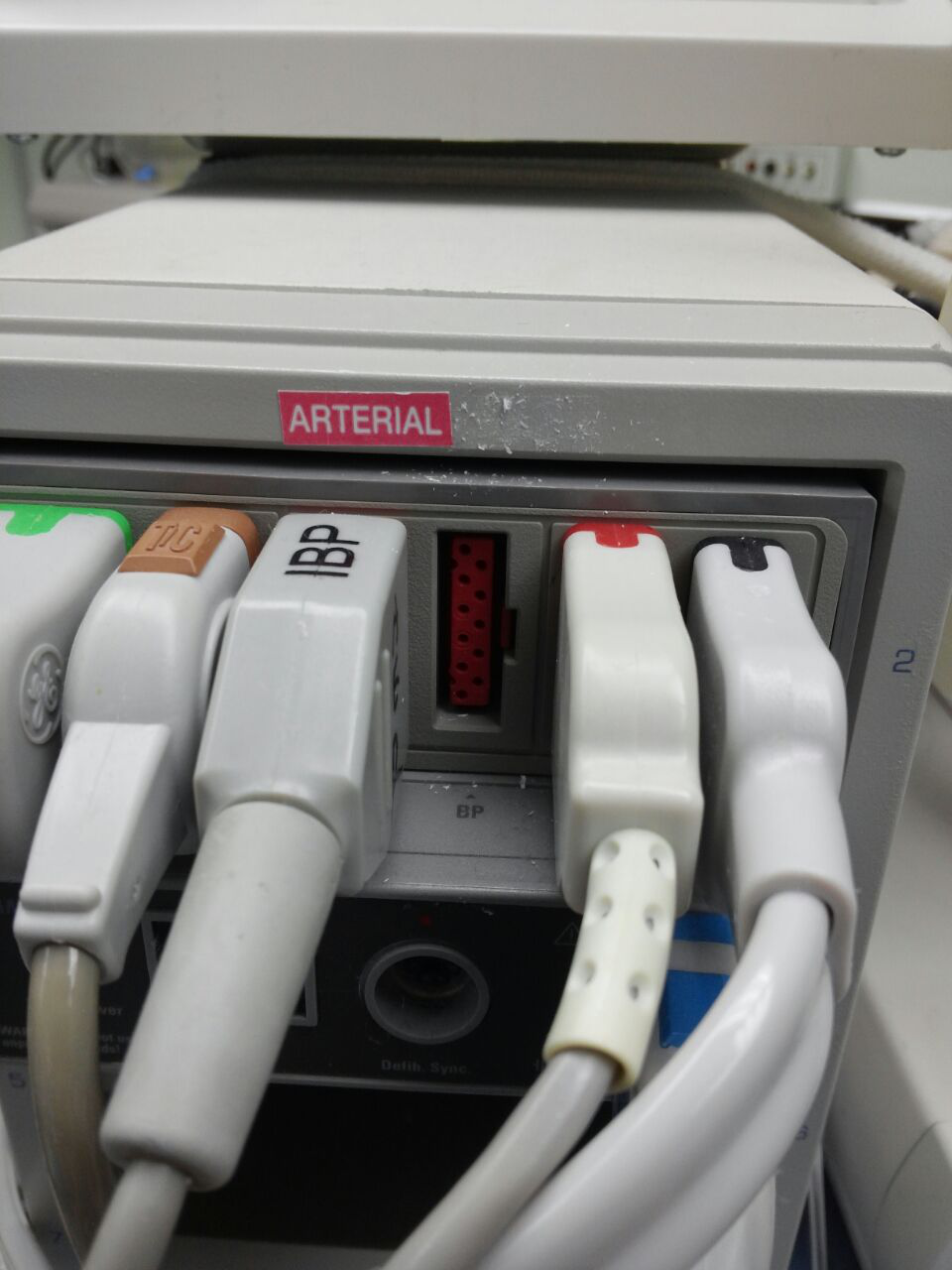
- Configuration for collecting both signals: connect the CVP transducer to BP3 and leave BP2 unused. Pin 3 provides CVP, and pin 13 provides PLETH. Assign the corresponding ADC channels to CVP and PLETH in Vital Recorder.
Vital Recorder Setup
- Add the device type corresponding to your ADC.
- Configure the connected analog channels and sampling rate according to the ADC guide.
- Assign each channel a track name and unit.
- Apply the appropriate signal scaling.
- Start recording and confirm that each channel contains the expected signal.
Troubleshooting
- A DataQ DI-1110 (or newer) is not recognised. These can run in either libusb or CDC mode, and Vital Recorder only recognises CDC mode — switch the device to CDC mode before use.
- Analog output scaling: ECG 1 V/mV ± 10%, invasive BP 1 V / 100 mmHg, SpO2 0–100 % equivalent to 0–1 V. Use these to set the per-channel gain and unit in Vital Recorder.
- ICP: when monitoring ICP, the ICP module must be in the first slot of the TRAM-RAC.
- Choosing an ADC: the DI-149 and DI-155 differ mainly in voltage resolution. The DI-149 is adequate for general monitoring; use the DI-155 if you intend to analyse ECG detail such as P- or T-waves.