Dräger Infinity Kappa
Note: No monitor-side configuration is required. Waveforms cannot be extracted over the Mini-D serial link; use the Analog/Sync port with an ADC instead.
| Cable | Adapter | Port | VR Device Name |
|---|---|---|---|
| 14-pin Mini-D ↔ DB-9F, custom (numeric) | None | X5 | Infinity |
| Analog/Sync cable → ADC (waveform) | None | X10 Analog/Sync port | — (ADC device) |
Connection Requirements
Dräger lists 5206441 as an export protocol cable and 4314618 as an analog output cable. Confirm compatibility and the cable termination for the installed configuration.
Cable Pinout
Numeric Data
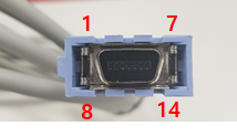
| Port | 14-pin Mini-D | → | DB-9F |
|---|---|---|---|
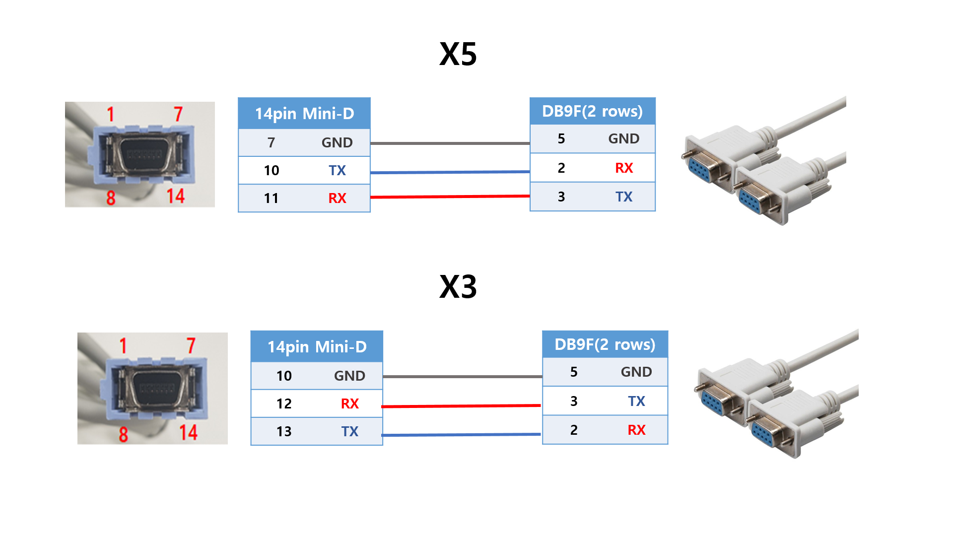
| X5 | 7 (GND) | → | 5 (GND) |
| X5 | 10 (TX) | → | 2 (RX) |
| X5 | 11 (RX) | → | 3 (TX) |
Analog Waveforms
| Analog/Sync Pin | Connection in the ADC Example |
|---|---|
| 12 | Channel 1 (+) |
| 13 | Channel 1 (−) |
| 7 | Channel 2 (+) |
| 6 | Channel 2 (−) |
Connection Steps
Numeric Data
- Locate the X5 port.
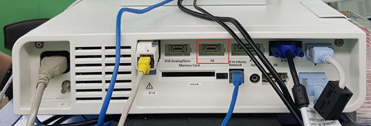
- Build the cable for the port you are using as shown in Cable Pinout, or use the Dräger factory cable (
5206441). - Connect the DB-9F end to the PC via a USB-Serial converter.
Waveform Data (Optional)
Waveforms are only available as analog voltages from the Analog/Sync port (Dräger part 4314618), read through an ADC (SNU-ADC, DataQ DI-149/DI-155, …).
Wire the ADC per Cable Pinout.
Device Configuration
No monitor-side configuration is required.
Vital Recorder Setup
- Add the device as
Infinityand select the PC serial port used for the connection.
Known Limitations
- Numeric data is delivered at a 2-second interval; do not expect higher-rate trends over this link.