GE Defib Connectors
Note: Use this route when the TRAM-RAC ANALOG OUT port is already occupied. ECG and ABP are available as voltages from the Defib. Sync connector on the front of the Tram / Patient Data Module. Like the TRAM-RAC analog port this is an analog output, so an ADC is required — the voltage scaling is the same.
| Cable | Adapter | Port | VR Device Name |
|---|---|---|---|
| 7-pin mini-DIN cable to ADC analog inputs (or an 8-pin mini-DIN with the center pin cut away) | — | Defib. Sync (front panel of the Tram / Patient Data Module) | (per ADC type) |
Connection Requirements
The ADC connects to the PC over USB. There is no separate VR device entry for the Defib.Sync port — add the ADC in Vital Recorder and map its channels.
Cable Pinout
Defib. Sync connector:
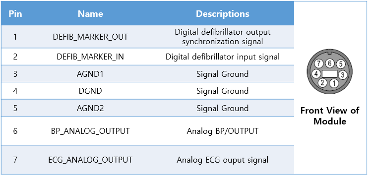
| Pin | Name | Description |
|---|---|---|
| 1 | DEFIBMARKEROUT | Digital defibrillator output synchronization signal |
| 2 | DEFIBMARKERIN | Digital defibrillator input signal |
| 3 | AGND1 | Signal ground |
| 4 | DGND | Signal ground |
| 5 | AGND2 | Signal ground |
| 6 | BPANALOGOUTPUT | Analog BP output |
| 7 | ECGANALOGOUTPUT | Analog ECG output |
- ECG channel: signal pin 7, ground pin 3.
- ABP channel: signal pin 6, ground pin 3 (or pin 5).
Connection Steps
- Locate the round Defib. Sync socket on the front panel of the module.
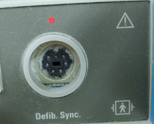
- Obtain a 7-pin mini-DIN cable. An 8-pin mini-DIN cable also fits if the center pin is cut away. Cut the far end off and wire the conductors you need to the ADC.
- Wire the ADC inputs as shown in Cable Pinout.
- Connect the ADC to the PC via USB and map the two channels in Vital Recorder.
Device Configuration
No configuration is required on the module — the analog outputs are always live. All setup happens on the ADC side in Vital Recorder: channel mapping, gain and unit (see Notes for the scaling values).
Vital Recorder Setup
- There is no Vital Recorder device entry for this port. Add the ADC (DataQ DI-149 / DI-155 / DI-1110 or SNU-ADC) as the device and map each analog channel to a track.
Known Limitations
- Only ECG and ABP are available here — for PLETH, RESP or additional pressures use the 15-pin TRAM-RAC ANALOG OUT port instead.
- Dash 4000: the defib cable pin mapping differs from the SNUADCM default, so a dedicated mapping (
Dash defib-SNUADCM) is needed rather than the stock channel map.
Notes
- Voltage scaling matches the TRAM-RAC analog output: ECG 1 V/mV ± 10%, invasive BP 1 V / 100 mmHg.